Accessories For Reaction Vessels
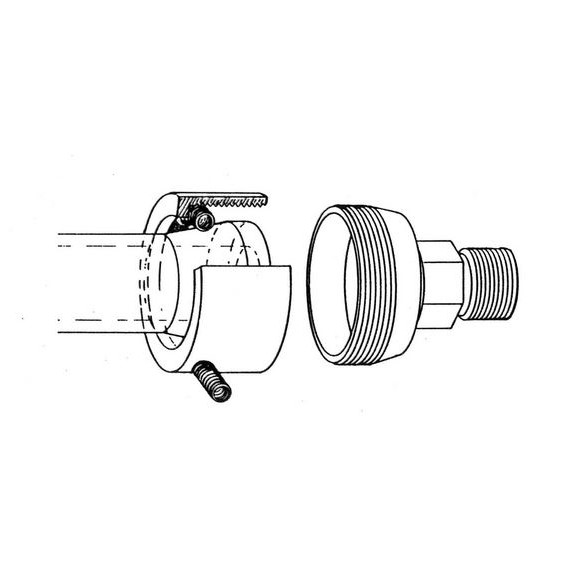

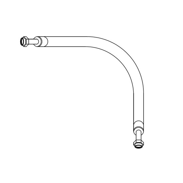
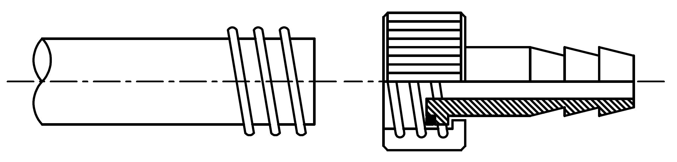
Thermal Jacket Joint
The thermal jacket joint is available in three versions:
with plastic olive (PGT/PTFE) for hoses with an internal diameter of 10mm.
Internal diameter of olive is 7mm.
Temperature Range: -10°C to max. +120°C
| Plastic olive straight | Article No. 4044 |
| Plastic olive angled | Article No. 4044/A |
| Metal adapter for thermostat hoses (DN15 to M16x1) | Article No. 4200 |
| Silicone sealant DN15 / Temperature range -40°C to +150°C | Article No. 4201 |
| PTFE sealant DN15 / Temperature range -180°C to +220°C | Article No. 4202 |
| Graphite sealant DN15 / for very high temperature +300°C | Article No. 4203 |
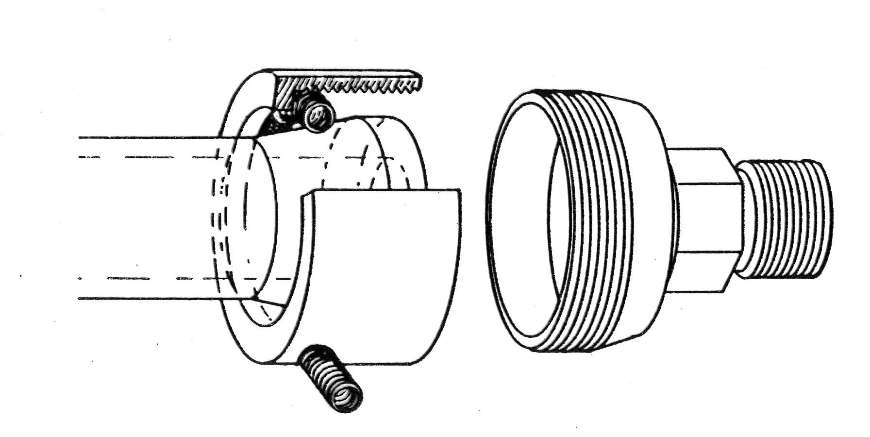
| Metal adapter for thermostat hoses (DN25 to M16x1) | Article No. 4205 |
| Silicone sealant DN25 / Temperature range -40°C to +150°C | Article No. 4206 |
| PTFE sealant DN25 / Temperature range -180°C to +220°C | Article No. 4207 |
| Graphite sealant DN25 / for very high temperature +300°C | Article No. 4208 |
Silicone O-rings
| For Flange | Article No. |
|---|---|
| NW60 | 4052 |
| NW100 | 4053 |
| NW120 | 4054 |
| NW150 | 4055 |
| NW200 | 4056 |
Silicone O-rings, FEP Covered, Seamless
| For Flange | Article No. |
|---|---|
| NW60 | 4057 |
| NW100 | 4058 |
| NW120 | 4059 |
| NW150 | 4060 |
| NW200 | 4061 |
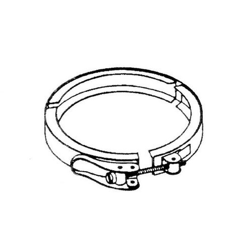
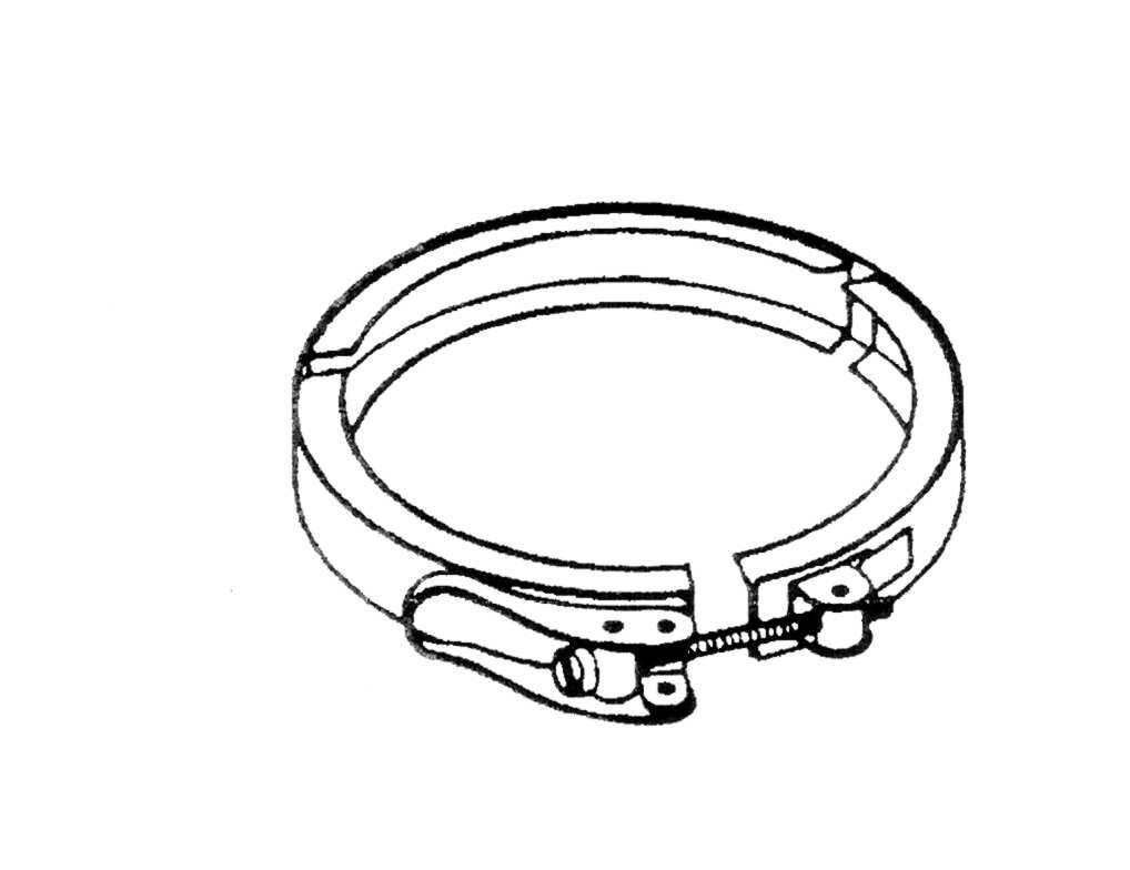
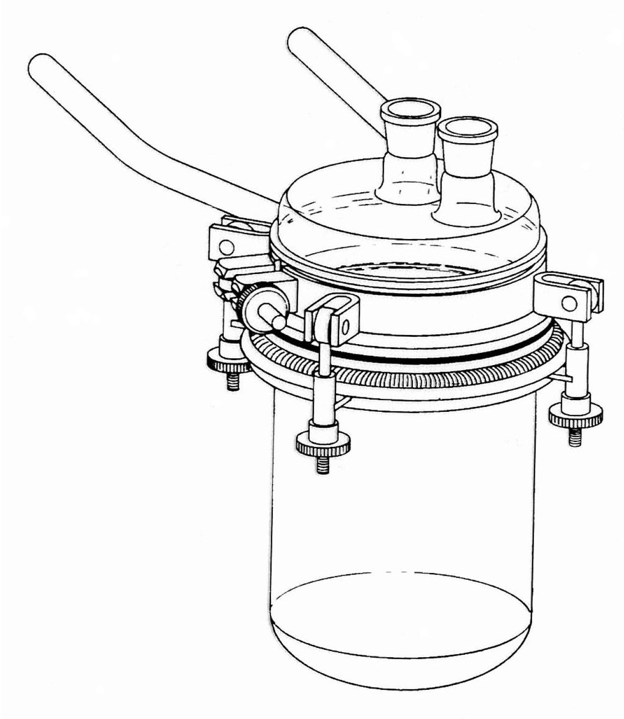
Quick Release Clamp Made Of Stainless Steel
| For Flange | Article No. |
|---|---|
| NW60 | 4047 |
| NW100 | 4048 |
| NW120 | 4049 |
| NW150 | 4050 |
| NW200 | 4051 |
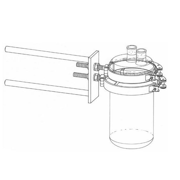
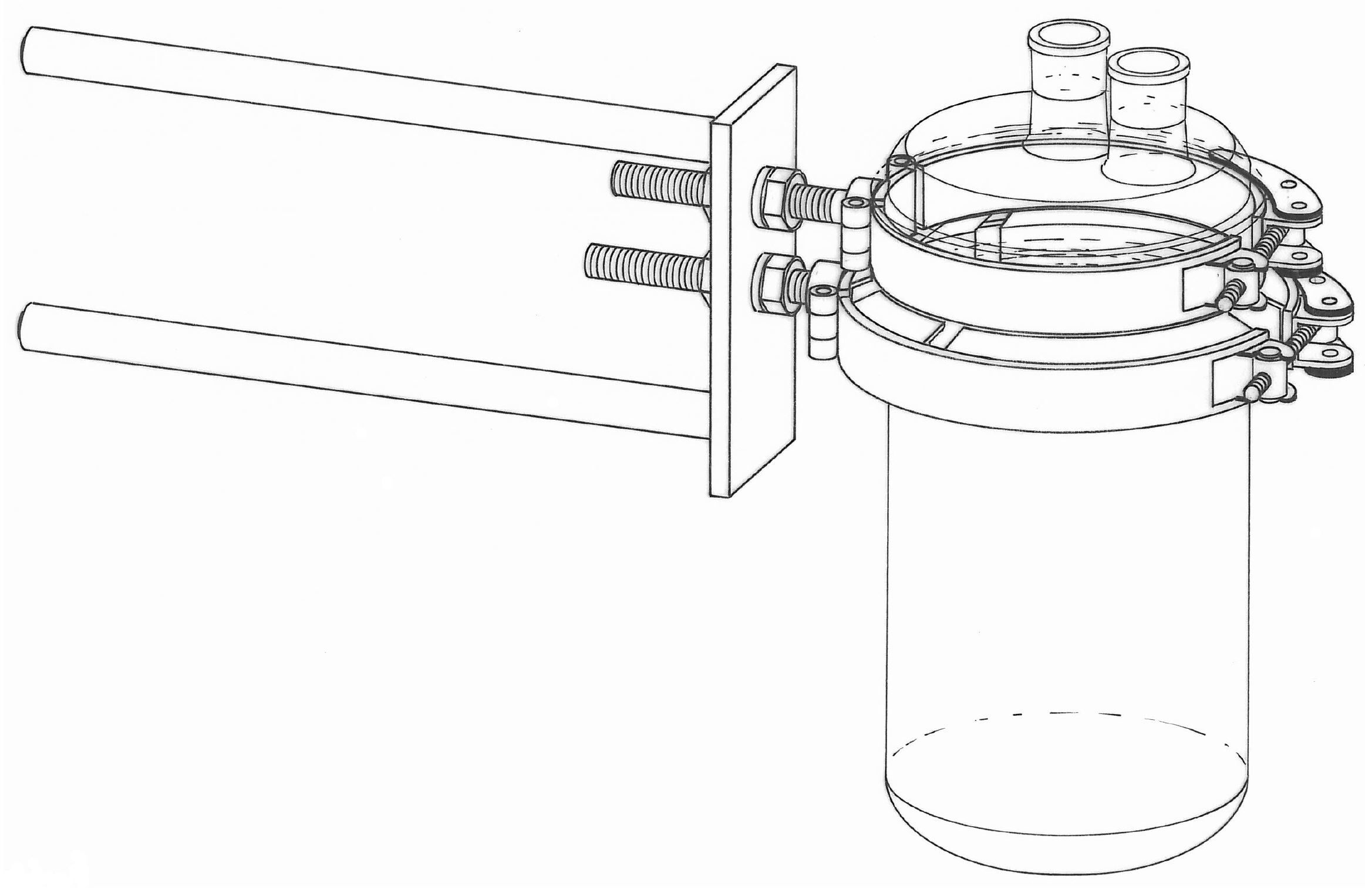
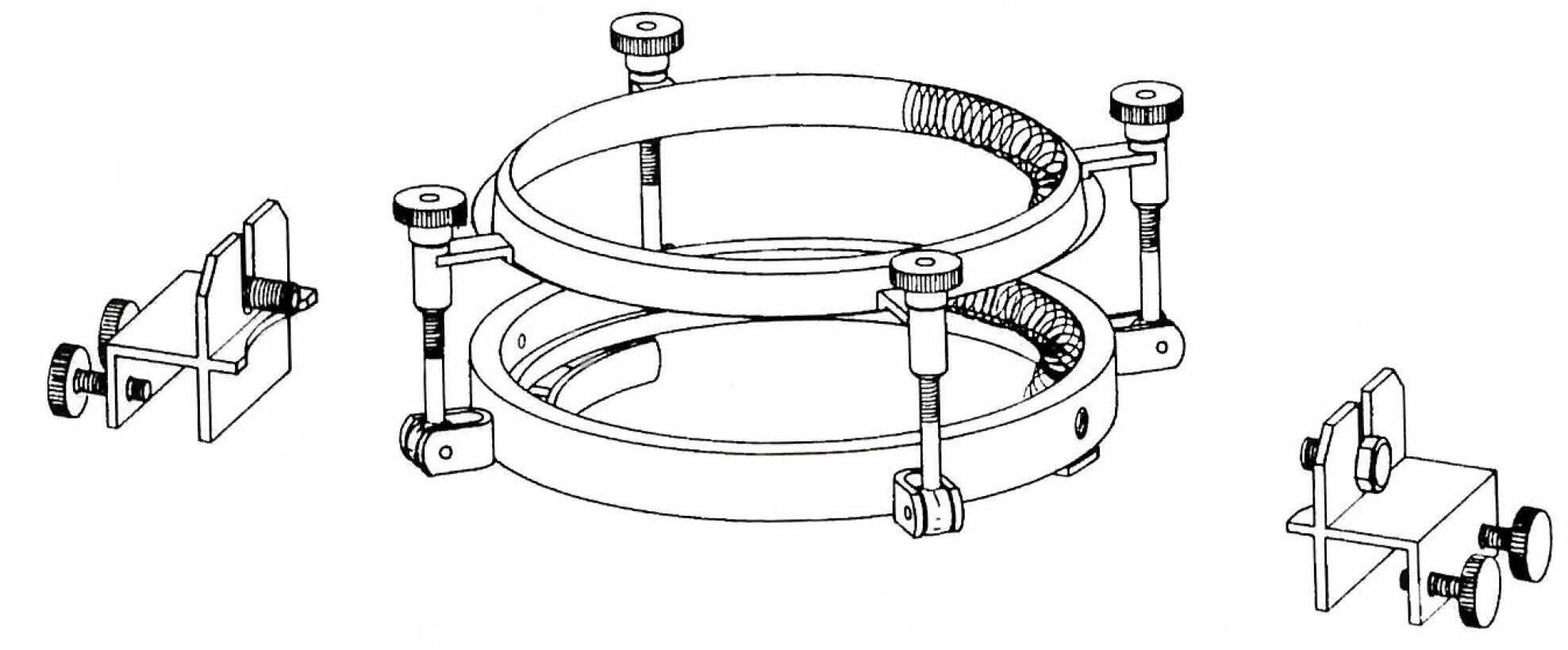
Quick Release Clamp Made Of Stainless Steel With Two Supporting Rods
| For Flange | Article No. |
|---|---|
| NW60 | 4260 |
| NW100 | 4261 |
| NW120 | 4262 |
| NW150 | 4263 |
| NW200 | 4264 |
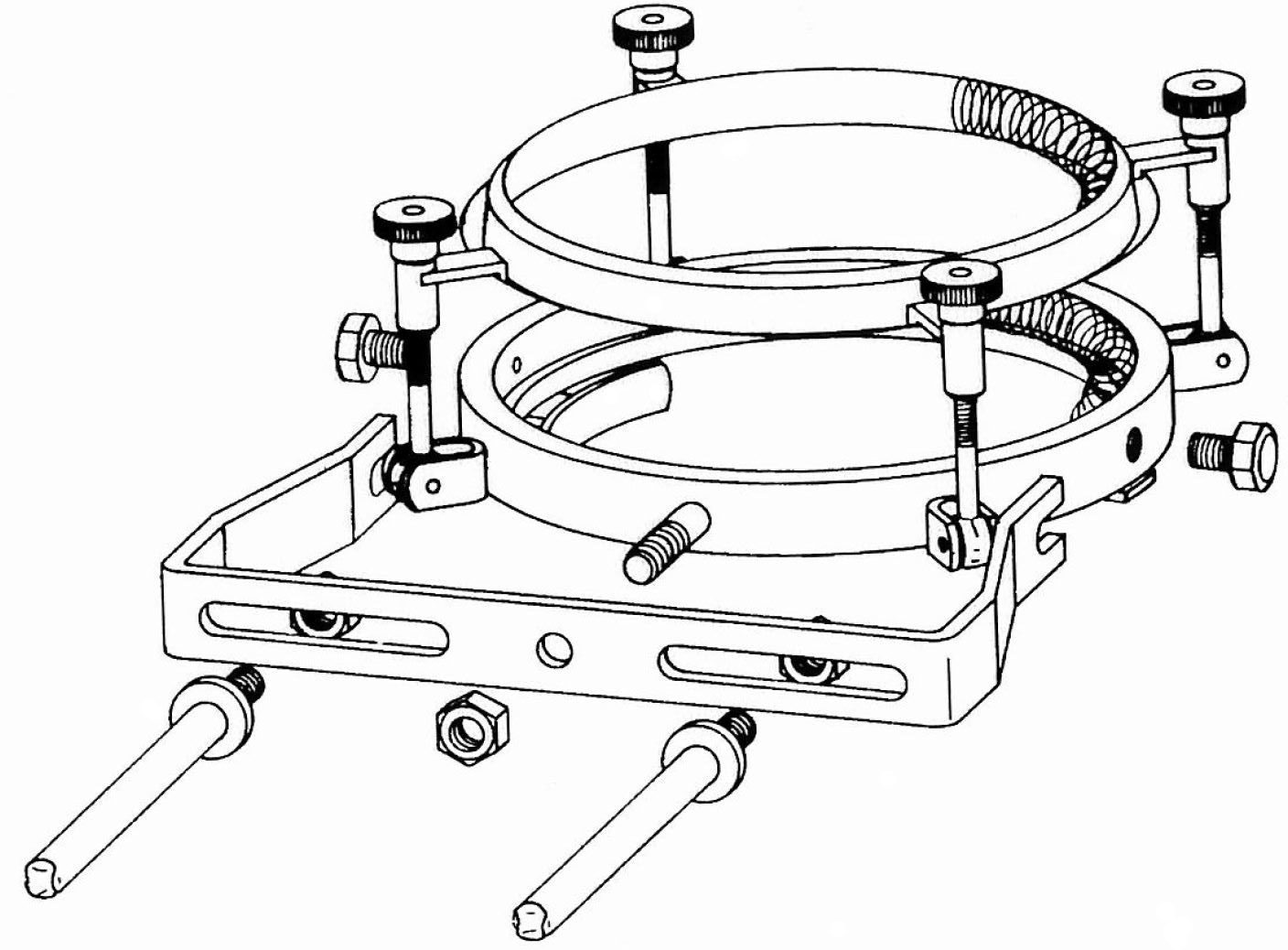
Double Holder "Vario-Grip"
This holder allows to remove the lid or vessel from the holder or the set-up without dismounting the set-up. The supporting rods can be utilised vertically or horizontally.
| For Flange | Article No. |
|---|---|
| NW60 | 4265 |
| NW100 | 4266 |
| NW120 | 4267 |
| NW150 | 4268 |
| NW200 | 4269 |
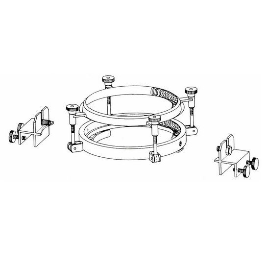
Universal Supporting Device Made Of Stainless Steel
massive version fror installation in a rod frame.
| For Flange | Article No. |
|---|---|
| NW100 | 4062 |
| NW120 | 4062/A |
| NW150 | 4063 |
| NW200 | 4064 |
Supporting Device
massive version fro installation in supporting frame, thickness supporting frame: standard 27mm, on request 13mm or 30mm
| For Flange | Article No. |
|---|---|
| NW60 | 4065/B |
| NW100 | 4065 |
| NW120 | 4065/A |
| NW150 | 4066 |
| NW200 | 4067 |
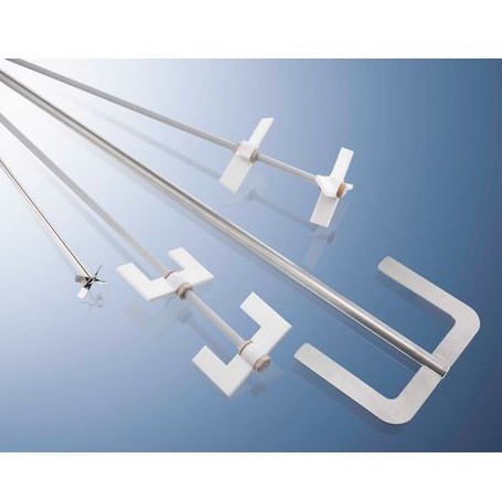
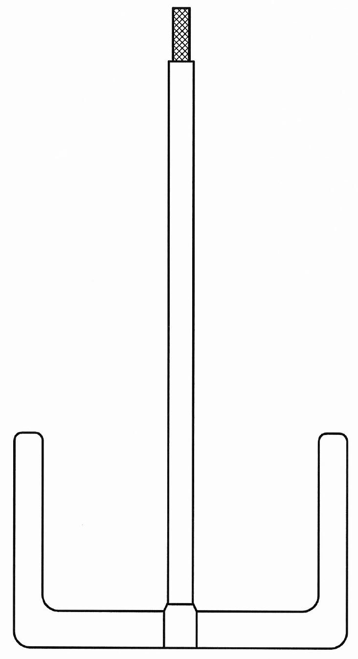
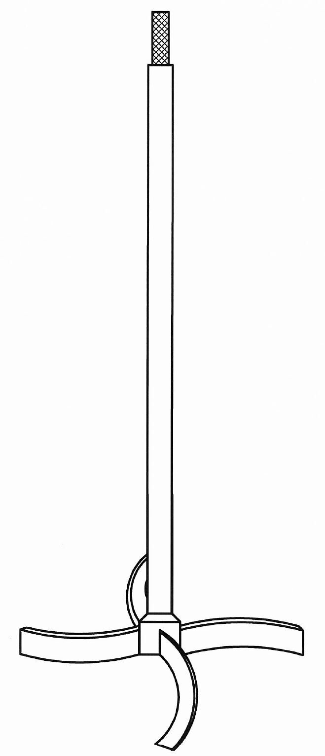
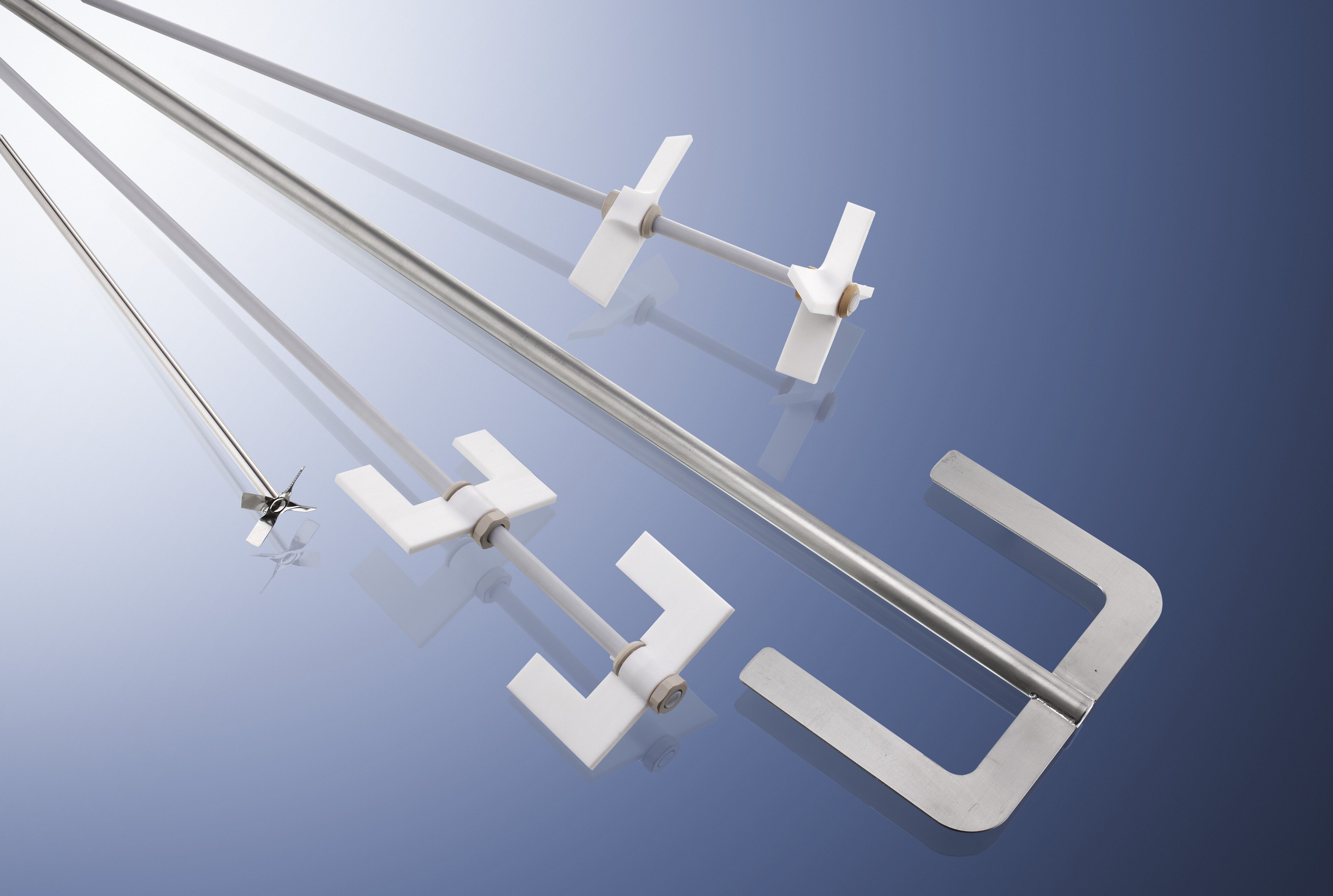
Stirrer Out of Glass and Stainless Steel
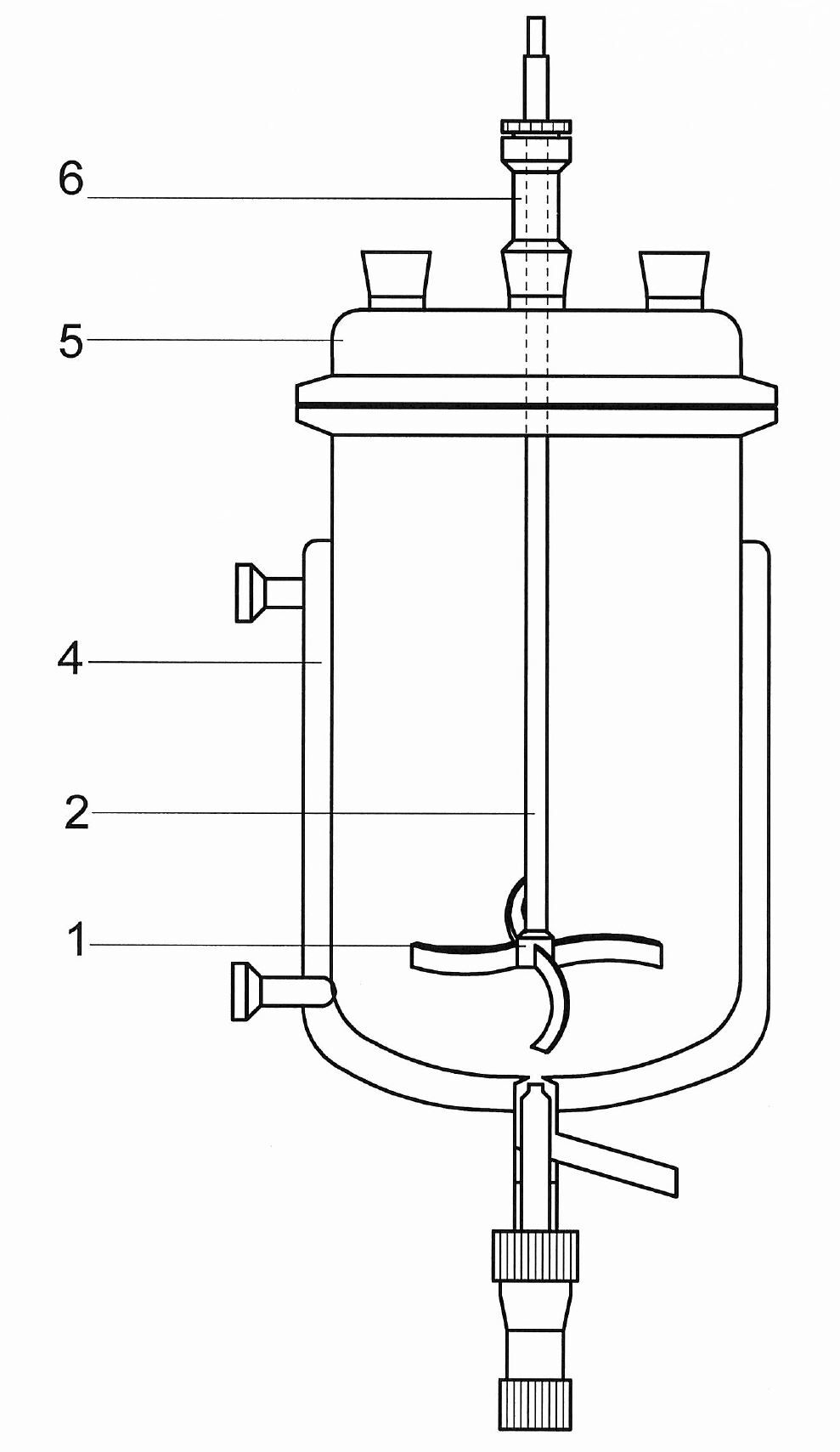
Following specifications are needed (please have a look at general drawing and example):
-
Type of stirrer
- Anchor stirrer with two arms: Article No. = AZ
- Anchor stirrer with four arms: Article No. = AV
- Propeller stirrer with three blades: Article No. = PD
- Propeller stirrer with four blades: Article No. = PV
- Second stage, marked with additional Z: Article No. = **Z
-

Type AZ -

Type PV -

Type PVZ
-
Shaft Diameter
- 8 mm: Article No. = W8
- 10 mm: Article No. = W10
- 16 mm: Article No. = W16
-
Material
- Glass: Article No. = G
- V4A: Article No. = V
- V4A: PFA coated: Article No. = PFA
-
Type Of Reactor
- Article No. = TRGN****
- or inner height of reactor and flange size
-
Type Of Lid
- Article No. = D****
- or total height of lid
-
Used Stirrer Seal
- Article No. = Art.No. of stirrer seal
- Type or article number
Stirrer out of V2A, PTFE coated
Following specifications are needed (please have a look at general drawing and example):
-
Type of stirrer
- Anchor stirrer with two arms: Article No. = AZ
- Anchor stirrer with four arms: Article No. = AV
- Propeller stirrer with three blades: Article No. = PD
- Propeller stirrer with four blades: Article No. = PV
- Second stage, marked with additional Z: Article No. = **Z
-
Shaft Diameter
- 8 mm: Article No. = W8
- 10 mm: Article No. = W10
- 16 mm: Article No. = W16
Type of stirrer Ø
NW60Ø
NW100Ø
NW120Ø
NW150Ø
NW200AZ 8 8 & 10 8 & 10 10 & 16 16 PZ 8 8 & 10 8 & 10 10 & 16 16 PD 8 8 & 10 8 & 10 10 & 16 10 &16 PV 8 8 & 10 10 10 & 16 10 &16 -
Material
- Article No. = B
-
Type Of Reactor
- Article No. = TRGN****
- or inner height of reactor and flange size
-
Type Of Lid
- Article No. = D****
- or total height of lid
-
Used Stirrer Seal
- Article No. = Art.No. of stirrer seal
- Type or article number
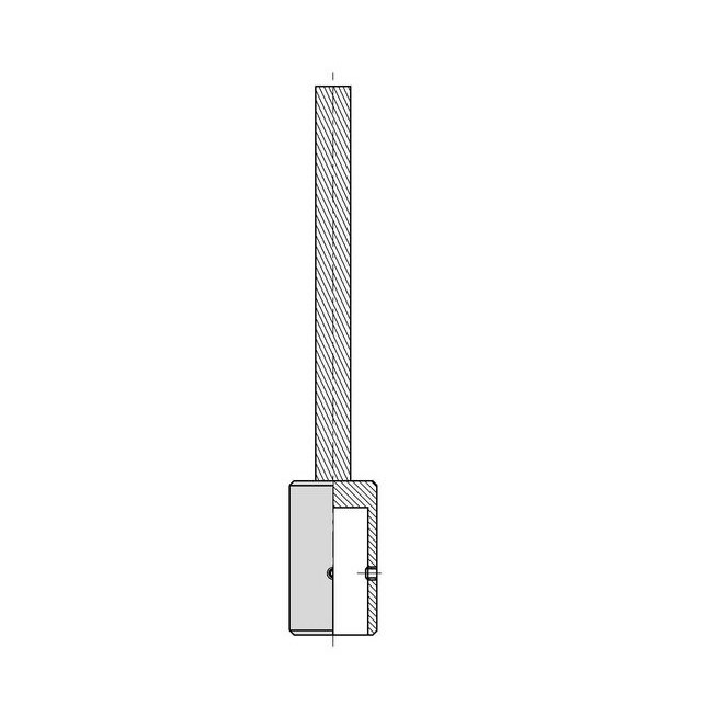
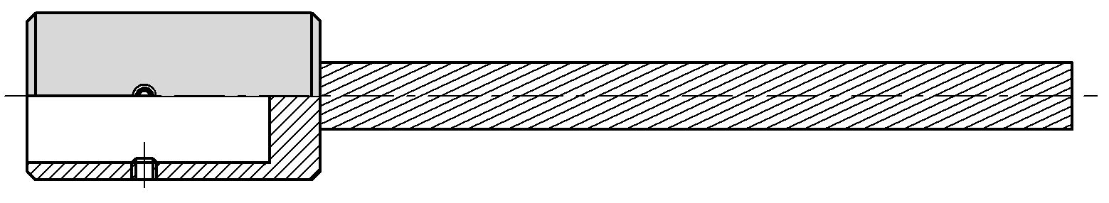
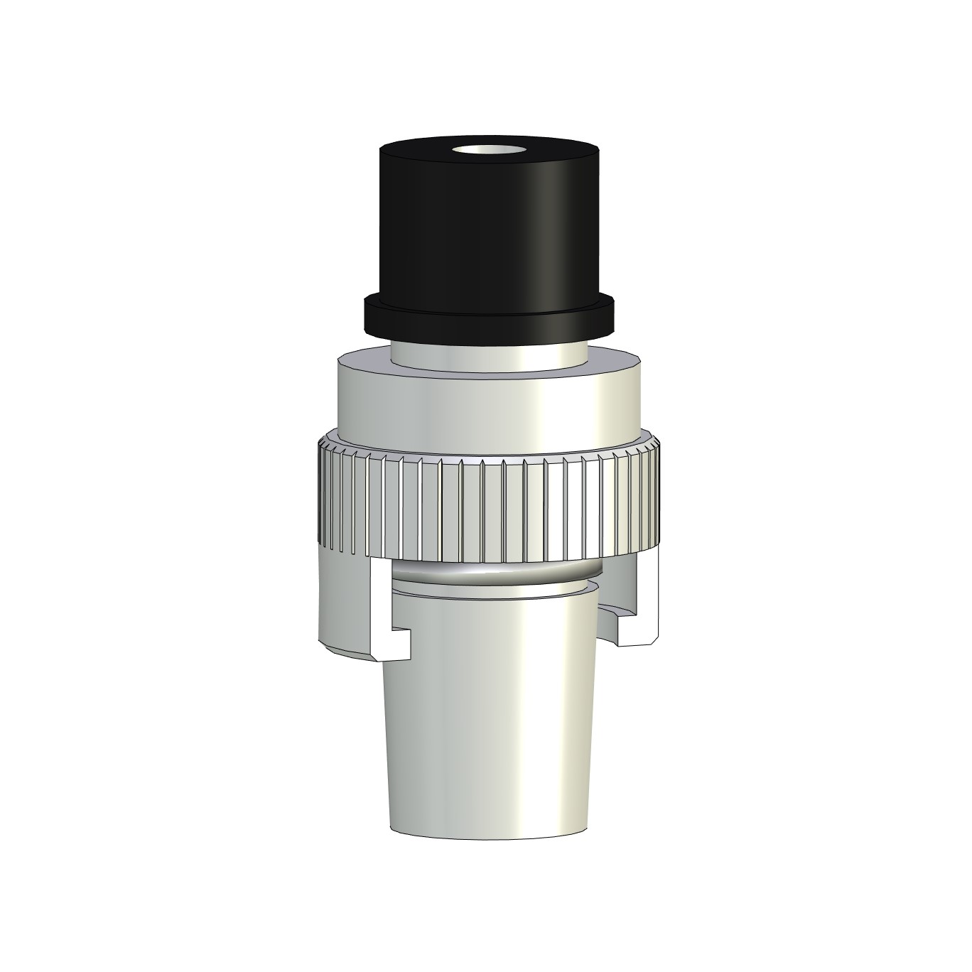
Coupling For Stirrers
Stirring couplings (stainless steel) are used to compensate any vibrations between stirrer and stirring tools
| Type |
Shaft
[mm] |
Article No. |
|---|---|---|
| RKS 8 | 8 | 40470 |
| RKS 10 | 10 | 40470 |
| RKS 16 | 16 | 40472 |
Stirrer Couplings with Headless Pins
for high torques; out of stainless steel
| Type |
Shaft
[mm] |
Material | Article No. |
|---|---|---|---|
| RKG 8/10 | 8 | V4A, PTFE | 404731 |
| RKG 13 | 13 | V4A | 404741 |
| RKG 14 | 14 | PTFE | 404751 |
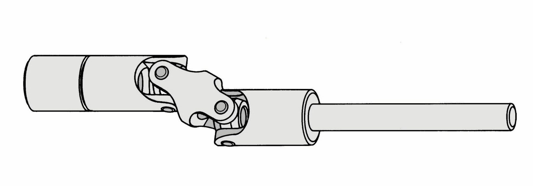
Couplings For Stirrers With Cardan
| Type |
Shaft
[mm] |
Article No. |
|---|---|---|
| RKK 10 | 6-8 | 40477 |
| RKK 16 | 12-14 | 40478 |
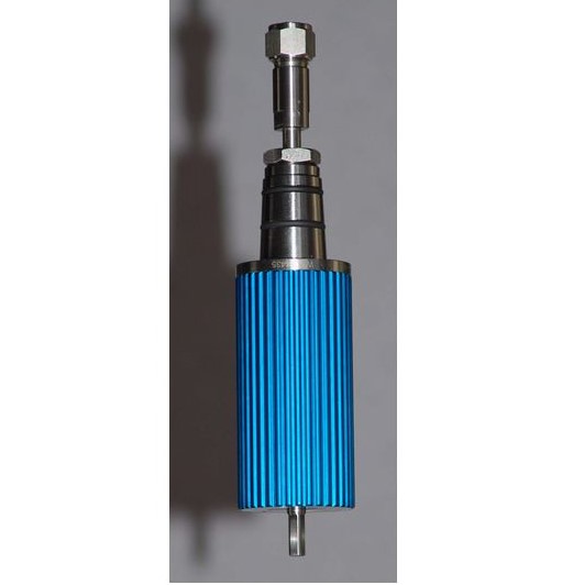
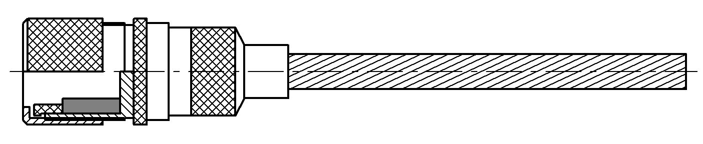
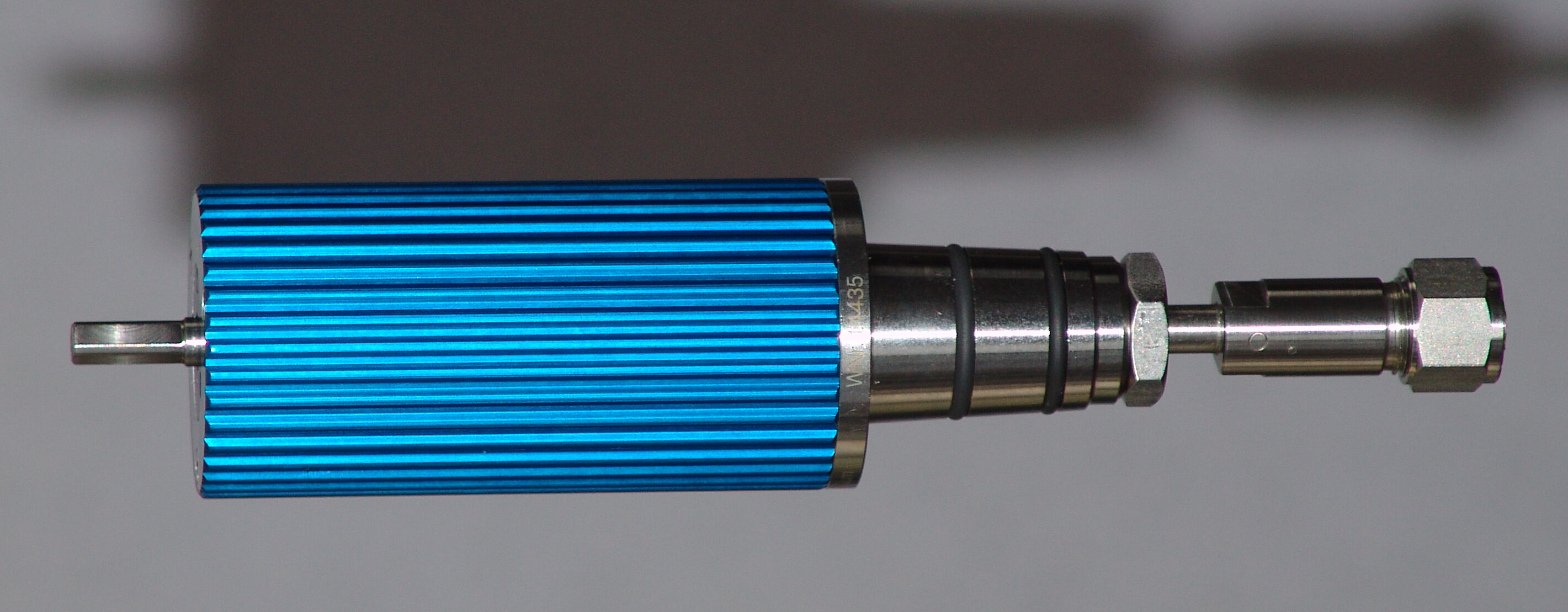
Magnetic Stirrer Seals
vacuum and magnetic stirrer-seal coupling out of stainless steel 1.4401 CrNiMo, with permanent magnets, absolutely gas- and vacuum-tight, for vacuum use, resistant against most acids and alkalines rot. 2.500 U/min.
| Type |
Conical Joint
NS |
Torque
[N/cm] |
for Shaft
[mm] |
Article No. |
|---|---|---|---|---|
| Typ MRK1/40 (NS29) | 29/32 | 40 | 8 und 10 | 404901 |
| Typ MRK1/60 (NS29) | 29/32 | 60 | 8 und 10 | 404911 |
| Typ MRK1/90 (NS29) | 29/32 | 90 | 8 und 10 | 404921 |
| Typ MRK1/120 (NS29) | 29/32 | 120 | 8 und 10 | 404931 |
| Typ MRK2/40 (NS45) | 45/40 | 40 | 8 und 10 | 404941 |
| Typ MRK2/60 (NS45) | 45/40 | 60 | 8 und 10 | 404951 |
| Typ MRK2/90 (NS45) | 45/40 | 90 | 8 und 10 | 404961 |
| Typ MRK2/120 (NS45) | 45/40 | 120 | 8 und 10 | 404971 |
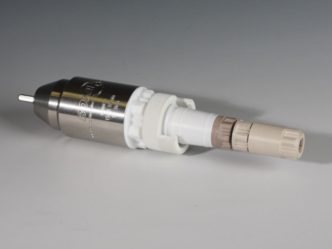
Magnetic Stirrer Seals
vacuum and magnetic stirrer-seal coupling out of PTFE / PEEK, with permanent magnets, absolutely gas- and vacuum-tight, for vacuum use, resistant against most acids and alkalines rot. 1.500 U/min.
| Type |
Conical Joint
NS |
Torque
[N/cm] |
for Shaft
[mm] |
Article No. |
|---|---|---|---|---|
| For stainless steel stirring shafts | ||||
| MRK-P NS29-8 | 29/32 | 90 | 8 | 404980 |
| MRK-P NS29-10 | 29/32 | 90 | 10 | 404981 |
| MRK-P NS45-10 | 45/40 | 90 | 10 | 404982 |
| For glass stirring shafts | ||||
| MRK-PG NS29-8 | 29/32 | 90 | 8 | 404983 |
| MRK-PG NS29-10 | 29/32 | 90 | 10 | 404984 |
| MRK-PG NS45-10 | 45/40 | 90 | 10 | 404985 |
Stirrer Seals Out of Glass
The KGW dynamic stirrer seal is suitable for both vacuum and excess pressure areas. It has two separate PTFE seals which can be adapted for excess and vacuum applications by altering of their mounting direction.
| Type |
Shaft
[mm] |
Conical
Joint |
Article No. |
|---|---|---|---|
| RV 8/29 | 8 | NS29 | 40461 |
| RV 10/29 | 10 | NS29 | 40462 |
| RV 16/29 | 16 | NS29 | 40463 |
| RV 8/45 | 8 | NS45 | 40464 |
| RV 10/45 | 10 | NS45 | 40465 |
| RV 16/45 | 16 | NS45 | 40466 |

PTFE-Stirrer Seals
for PTFE-coated V2A stirrers
| Type |
Shaft
[mm] |
Conical Joint | Article No. |
|---|---|---|---|
| RVFE 8/29 | 8 | NS 29/32 | 40451 |
| RVFE 10/29 | 10 | NS 29/32 | 40452 |
| RVFE 10/45 | 10 | NS 45/40 | 40453 |
| RVFE 16/45 | 16 | NS 45/40 | 40454 |
PTFE-Stirrer Seals with rotary protection
for PTFE-coated V2A stirrers
| Type |
Shaft
[mm] |
Conical Joint | Article No. |
|---|---|---|---|
| RVFE 10/29 | 10 | NS 29/32 | 40452-S |
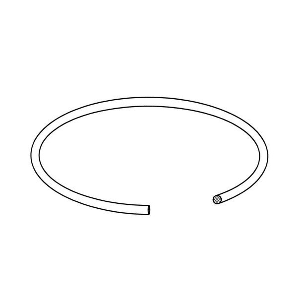
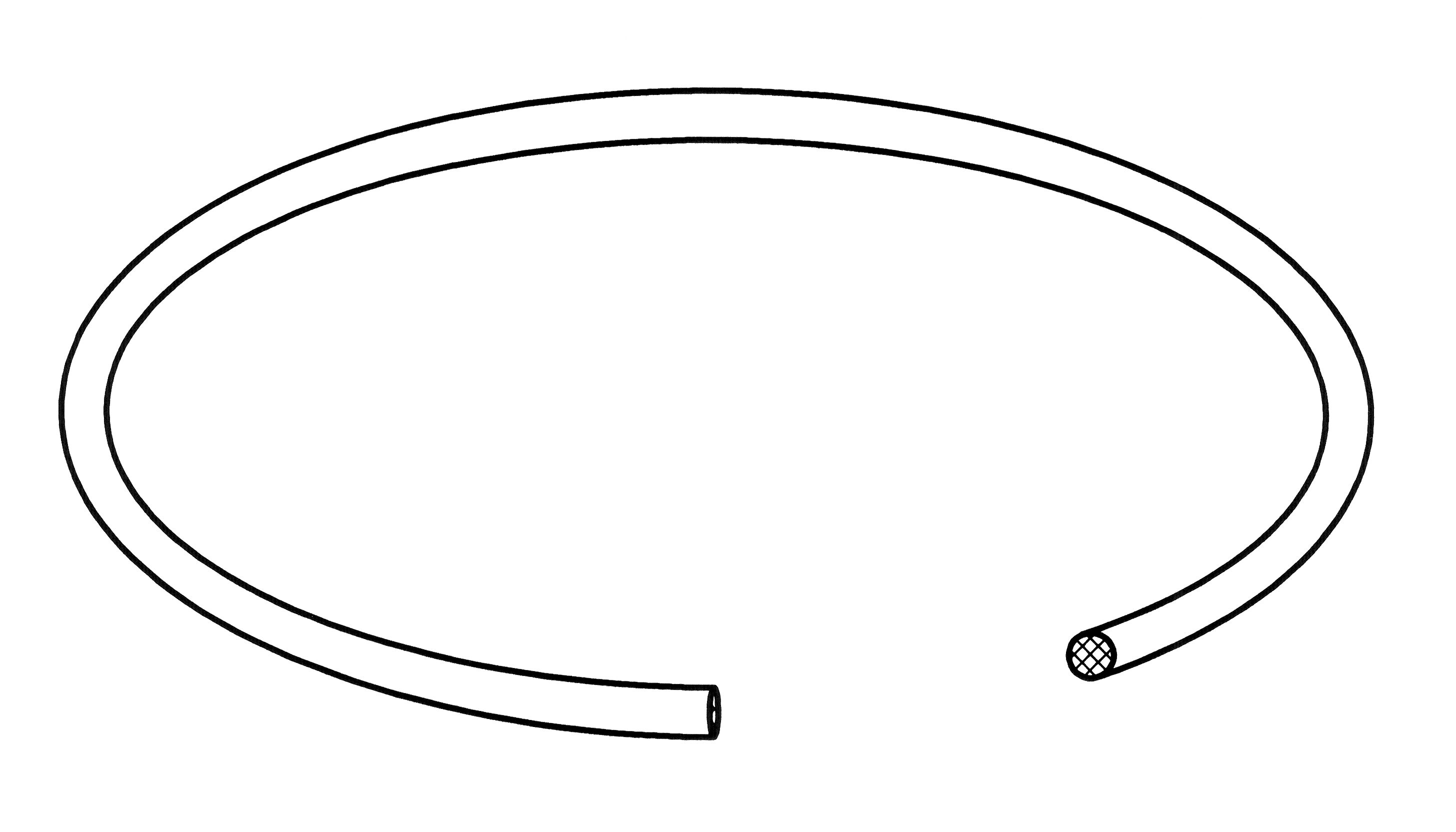
Metal Hoses
thermally insulated, with M16x1 threaded joints on both sides, matches to standard threads of circulation thermostats, max. operating temperature +300° C.
|
Length
[m] |
Article No. |
|---|---|
| 0,5 | 4215 |
| 1,0 | 4216 |
| 1,5 | 4217 |
| 2,0 | 4218 |
